
5F, W2, Chengxin Building , Tian An Shen Chuang Valley Industrial Center, Fenggang Town, Dongguan City, Guangdong Province,China 523681
Views: 0 Author: Site Editor Publish Time: 2026-08-03 Origin: Site


Upgrading physical security and access control systems often faces a severe bottleneck. Legacy edge devices usually lack native Power over Ethernet support. You will frequently find this issue across older IP cameras, electronic door strikes, and biometric readers. Pulling new high-voltage electrical lines to every door and camera location is prohibitively expensive. It also requires extensive labor and building downtime.
Instead, you can utilize existing IT network infrastructure to power these non-PoE endpoints safely. This approach avoids heavy electrical retrofits. It bridges the gap between modern network switches and older edge devices seamlessly.
This guide breaks down how to evaluate, specify, and deploy 10/100Mbps splitter hardware effectively. You will learn to bridge modern network switches with legacy security infrastructure. We will show you how to ensure continuous uptime and strict IT compliance. By following these steps, you can modernise your facility's physical security without disrupting core operations.
Cost Avoidance: Utilizing standard network infrastructure to power 12V/24V non-PoE edge devices eliminates the need for licensed electricians during retrofits.
Bandwidth Appropriateness: 10/100Mbps (Megabit) throughput provides more than adequate bandwidth for access controllers and standard CCTV, offering a highly cost-effective alternative to unnecessary Gigabit hardware.
Infrastructure Protection: Selecting IEEE 802.3 compliant (active) splitters protects sensitive legacy hardware from voltage spikes through proper power negotiation.
IT & Security Alignment: Deploying security edge devices on standard network topologies allows for centralized UPS battery backup and secure VLAN segmentation.
You must differentiate deployment realities when planning facility security. Greenfield projects allow architects to specify end-to-end PoE hardware from day one. However, legacy retrofits present a different challenge. You must bridge existing non-PoE door controllers and older cameras with modern network switches. Tearing out functional legacy hardware just for network compatibility wastes budget.
Delivering power efficiently drives the core business case. Compare the cost of installing local AC outlets near every access point versus utilizing existing network drops. Hiring licensed electricians to run high-voltage conduit is expensive. It also triggers rigorous safety inspections. Centralizing power through data lines bypasses these hurdles completely. You leverage cables already resting in your ceiling plenums.
Centralized uptime adds tremendous security value. Physical security systems must survive building power outages. Splitting power at the network edge allows access control and CCTV systems to piggyback on the IT server room's uninterruptible power supply (UPS). If the main grid fails, your network switch remains powered. In turn, it continues feeding power downstream. Your mag-locks remain secured, and your cameras keep recording.
Network power deployment utilizes several distinct devices. Understanding their specific roles prevents costly architectural errors.
A splitter acts as the receiving end at the device location. It takes incoming PoE from a network switch. It then splits the unified signal into two separate streams. One stream provides standard Ethernet data. The other outputs a dedicated DC power feed. You typically connect this power feed via a barrel jack or terminal block to your non-PoE device. This allows legacy security readers to operate on modern network drops.
An injector performs the exact opposite function of a splitter. It serves as the source component. You use an injector to add power to a standard data line. This is necessary when your main network switch lacks native PoE capabilities. It injects power into the cable run rather than extracting it at the edge.
Extenders serve a very different purpose. Standard Ethernet cable limits data transmission to 100 meters. Extenders boost this signal to push past the standard distance limit. They do not alter the power format. Conversely, a PoE Converter specifically adapts the voltage format for end-device compatibility. It drops or steps up the voltage to match what the edge device safely requires.
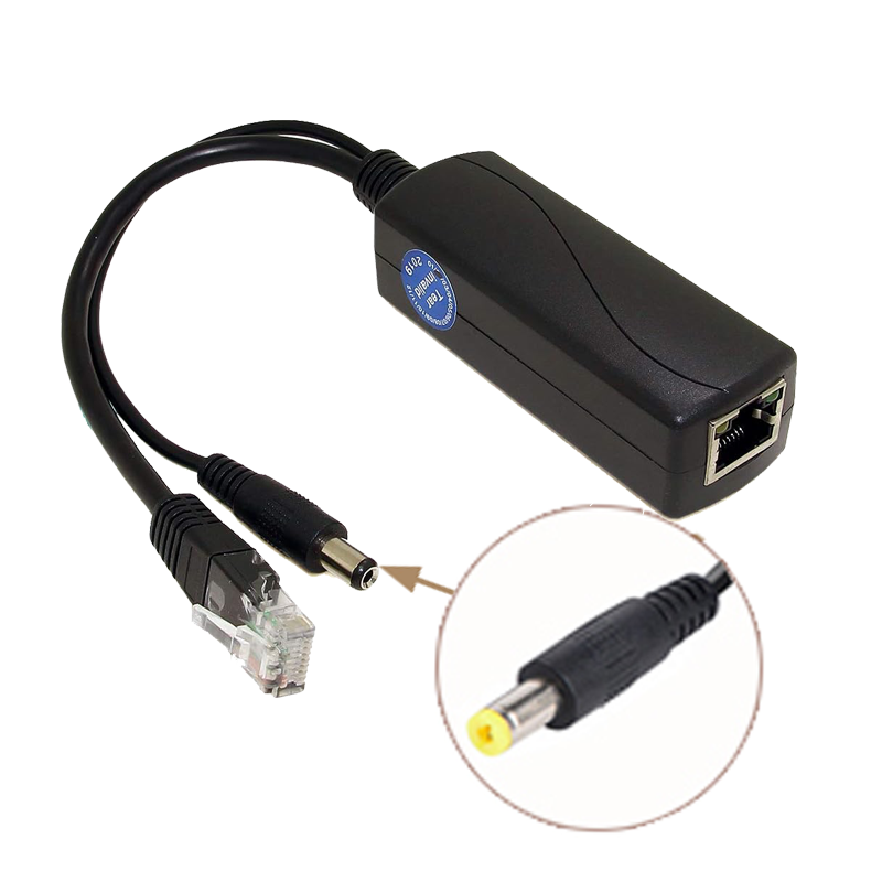
Selecting the right endpoint hardware ensures system longevity. You must match equipment specifications exactly to your security devices.
Enterprise environments require Active (IEEE 802.3af/at compliant) hardware. Active units execute a digital handshake with the upstream switch. They negotiate specific power requirements before the switch delivers any voltage. This active negotiation prevents overloading. It protects sensitive non-compliant edge hardware from frying. Passive units skip this handshake. They blast continuous voltage down the line, which poses a severe fire and hardware risk.
You must verify output requirements carefully. A splitter’s DC output must match the access reader or camera exactly. Common security devices require 5V, 12V, or 24V. Supplying 24V to a 12V camera will destroy the device instantly. Pay close attention to barrel jack pinouts as well. Ensure the center pin polarity aligns with your device's input port.
Do not overpay for unnecessary bandwidth. A standard RFID card reader transmits tiny kilobyte data packets. Even a standard 1080p IP security camera utilizes only a fraction of 100Mbps. Prioritizing a Megabit POE Splitter keeps your hardware costs incredibly low. It handles access control traffic perfectly without sacrificing operational latency.
Security devices often live in harsh environments. Evaluate the splitter's industrial-grade housing and heat dissipation limits. Devices deployed in unventilated ceiling plenums get extremely hot. Outdoor junction boxes bake in direct sunlight. Choose units rated for extreme temperature fluctuations to prevent hardware lockups.
Device Type | Typical Bandwidth Need | Typical Voltage | Recommended Solution |
|---|---|---|---|
RFID Access Reader | < 1 Mbps | 12V / 24V | Megabit Splitter (10/100) |
1080p IP CCTV Camera | 4 - 8 Mbps | 12V | Megabit Splitter (10/100) |
Biometric Scanner | 1 - 2 Mbps | 12V | Megabit Splitter (10/100) |
Multi-Sensor 4K Camera | 15 - 25 Mbps | 24V / PoE+ | Gigabit Hardware (if needed) |
Deploying physical security on an IT network requires strict operational compliance. Security integrators and IT departments must collaborate closely.
You must map splittered edge devices to a dedicated security VLAN. Mixing physical security data with standard corporate traffic introduces major risks. A dedicated VLAN prevents broadcast storms from crashing door controllers. It also secures the physical perimeter. If a bad actor unplugs an outdoor camera, VLAN isolation prevents them from accessing internal company servers.
Your upstream switch acts as the Power Sourcing Equipment (PSE). You must calculate the total wattage draw across all ports. Switches possess a finite overall power capacity. If you deploy forty 15W door controllers on a switch rated for only 250W total, the switch will fail. Map out your Class 0-4 power requirements in advance.
Class 1: Very low power (Up to 3.84W)
Class 2: Low power (Up to 6.49W)
Class 3: Mid power (Up to 12.95W - typical for legacy cameras)
Class 4: High power (Up to 25.5W - typical for multi-door controllers)
The physical layer dictates power delivery success. Your installed PoE Cable must utilize pure solid copper conductors. Copper-Clad Aluminum (CCA) cables are cheaper but perform poorly with power transmission. CCA leads to severe voltage drops over long distances. This drop causes intermittent door lock failures and random camera reboots. Always verify cable integrity before deploying power over data lines.
Follow a strict deployment protocol to ensure stable system operation. Before starting, conduct a pre-installation audit. Verify your non-PoE device's exact voltage and amperage limits. Confirm your upstream switch port is properly configured and enabled for power delivery.
Step 1: Terminate and Test. Run your category cable to the deployment site. Terminate the ends properly. Use a network tester to verify data continuity. Test for active power voltage presence at the edge location before plugging in any devices.
Step 2: Component Connection. Take the incoming network line and plug it securely into the splitter's labeled "PoE IN" port. Ensure the connection clicks into place.
Step 3: Power and Data Separation. Connect the splitter's DC power output barrel directly into the legacy camera or door controller. Next, connect the resulting standard data cable from the splitter into the device's network port.
Step 4: IT Handshake and Verification. Log into the switch management console. Monitor the port to verify stable power draw. Establish that the network link status is active. Finally, confirm the device registers correctly on the designated security VLAN.
Even with careful planning, edge deployments occasionally encounter issues. You can diagnose most failures quickly by checking a few common culprits.
End devices sometimes enter continuous reboot cycles. This boot loop typically indicates a mismatch in the power class. It can also mean you depleted the upstream switch's total power budget. Alternatively, excessive cable length causes a severe voltage drop. If the device expects 12V but only receives 9.5V at the end of a long run, it will constantly restart.
Sometimes the switch shows an active port light, but no data transmits. Address port configuration mismatches first. Check if spanning tree protocol blocked the port accidentally. You should also inspect the Ethernet termination. Damaged internal data pairs within the RJ45 connector often transmit power successfully while failing to pass network data.
Splitters may drop offline during peak afternoon hours. This indicates thermal shutdown. Improper external enclosures trap ambient heat generated by the hardware. Move the equipment to a ventilated junction box. Alternatively, upgrade to a device with a wider industrial temperature tolerance rating.
Deploying targeted network power accessories offers immense strategic value. You extend the functional life of legacy physical security hardware while modernizing the building's infrastructure. By routing power through existing data lines, you eliminate costly electrical contracting bills.
When selecting hardware, always prioritize IEEE compliance and exact voltage matching over raw throughput speeds. An active 10/100Mbps unit handles access control perfectly while keeping budgets manageable. Check environmental ratings carefully if deploying outside of climate-controlled server rooms.
Your next step requires immediate coordination with your IT team. Advise your security integrators and network managers to conduct a comprehensive power-budget audit. Pilot a single-door or single-camera deployment first. This validates hardware compatibility and VLAN configurations before you execute a facility-wide rollout.
A: Yes. The switch automatically auto-negotiates the port speed down to the 10/100Mbps hardware capability of the splitter. This preserves data integrity perfectly while still delivering the necessary power to your edge device.
A: Network outages pause remote data monitoring. However, if your upstream PoE switch runs on a centralized server room UPS, it remains powered. The downstream splitter will continue providing uninterrupted DC power, keeping your mag-locks or electric strikes functioning safely.
A: No. A splitter is strictly a physical layer power-handling component. It does not have an IP address, firmware, or an operating system to be exploited. Network security relies entirely on your upstream switch configuration and proper VLAN isolation.


