
5F, W2, Chengxin Building , Tian An Shen Chuang Valley Industrial Center, Fenggang Town, Dongguan City, Guangdong Province,China 523681
Views: 0 Author: Site Editor Publish Time: 2026-08-17 Origin: Site


Upgrading your network infrastructure to modern 48V Power over Ethernet brings incredible efficiency and centralized control. You can manage data and power simultaneously from a single rack. But this technological leap forward often leaves perfectly functional older equipment behind. You suddenly face a massive compatibility gap. Non-PoE access control panels, analog-to-IP cameras, and older VoIP phones cannot handle raw 48V inputs. Connecting these legacy endpoints straight into a high-voltage switch spells immediate disaster. Without proper step-down regulation, you risk catastrophic equipment failure or severe network-wide electrical feedback.
You need a safe, reliable bridge between modern power sourcing equipment and legacy edge devices. An active Megabit POE Splitter serves as this critical link. It safely decouples data from power, negotiates the necessary IEEE protocol handshake, and drops the voltage to safe levels. This decision-stage engineering guide helps you evaluate, size, and safely deploy these splitters. Read on to master mixed-device integration and protect your valuable network assets.
Voltage is strict; Amperage is a ceiling: A 12V device will pull only the current it needs. Over-speccing a splitter’s amperage (e.g., using a 2A splitter for a 1A device) is safe and often recommended for stability.
Demand Active Isolation: Passive splitters bypass protocol handshakes and lack surge isolation, creating high-risk points of failure. Look for active splitters with ≥1500 VRMS isolation.
Bandwidth Matching: A Megabit POE Splitter (10/100Mbps) is highly cost-effective for legacy cameras and sensors, but Gigabit models are required for high-throughput endpoints like video walls or modern IT endpoints.
Installation Sequence Matters: Connecting the DC output before establishing the data/power line can result in regulator burnout due to power surges.
Modern PoE switches adhere to IEEE 802.3af and 802.3at standards. These enterprise switches output direct current anywhere between 44V and 57V. This 48V reality ensures power can travel long distances over thin copper wires. However, legacy edge devices simply cannot process this voltage. They typically require 5V, 12V, or occasionally 24V DC to function. Pushing 48V into a 12V integrated circuit instantly destroys the device.
This is where the splitter plays a mandatory role. A standard splitter physically and electrically separates the combined Ethernet line. It takes the incoming PoE cable and divides the signals. It routes the data securely to a standard RJ45 cable. Simultaneously, it routes the power through an internal transformer, outputting regulated current to a DC barrel jack or Type-C port.
You cannot simply splice Ethernet wires to extract power. Standard switches operate intelligently. They require a specific protocol handshake before they ever release 48V into the line. The switch checks for a valid 25k-ohm resistance signature from the endpoint. If the endpoint lacks this signature, the switch outright refuses to send power. Active splitters spoof this handshake securely. They present the correct signature to the switch, extract the power, and step it down. This active negotiation allows you to power non-network electrical devices, like LED yard lighting, directly from your IT switch.
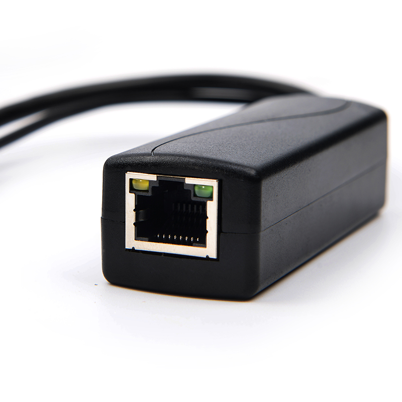
Choosing the correct voltage output forms the foundation of network stability. You must strictly match the splitter's output voltage to the endpoint's input requirement. Any deviation here guarantees failure. The market broadly divides into 5V and 12V categories.
Low-voltage electronics heavily rely on the 5V ecosystem. A dedicated 5V PoE Splitter perfectly serves these micro-computing environments.
Target endpoints: Raspberry Pi clusters, iPads serving as kiosks, IoT environmental sensors, and legacy Dropcams.
Interface trends: USB Type-C rapidly dominates this sector. It replaces older micro-USB cables and bare barrel jacks. Type-C provides a more secure mechanical fit and supports higher amperage ceilings.
Security perimeters and audio-visual installations lean entirely on 12V architectures. You will deploy a 12V PoE Splitter for heavier standalone equipment.
Target endpoints: Legacy IP cameras, motorized PTZ models, access control panels, and independent AV transceivers.
Interface trends: The standard 5.5x2.1mm DC barrel connector remains the absolute industry standard here. You will rarely find Type-C in older 12V security hardware.
Many technicians fundamentally misunderstand amperage. They fear a high-amperage splitter will force too much current into a small device. We must clarify this electrical rule: load determines draw. Voltage pushes, but the device pulls current.
Using a 12V 2A (24W) splitter to power a 12V 0.5A (6W) camera is completely safe. The camera only "pulls" the 0.5A it requires to operate. The splitter simply possesses a higher capacity. Under-speccing amperage causes immediate issues. If you use a 1A splitter for a 2A device, the endpoint will suffer reboot loops. It will constantly starve for power. Conversely, over-speccing the splitter guarantees thermal stability. The internal components of an over-specced splitter run much cooler because they operate well below their maximum threshold.
Splitter Type | Typical Connectors | Common Endpoints | Average Wattage Draw |
|---|---|---|---|
5V | Type-C, Micro-USB | Raspberry Pi, Tablets, Sensors | 10W - 15W |
12V | 5.5x2.1mm DC Barrel | IP Cameras, Access Control | 12W - 24W |
Not all splitters offer the same protection. You will find drastic differences in internal architecture. Understanding these architectures prevents catastrophic network damage.
You must distinguish between active and passive models during the procurement phase.
Passive Splitters: These units merely split physical wires. They provide zero step-down regulation and perform no protocol handshake. They assume the power source already outputs the exact required voltage. Plugging a passive splitter into a 48V active switch creates a high risk of frying 12V devices instantly. You should only use them in closed, proprietary 12V/24V injector setups.
Active Splitters: These units contain dedicated integrated circuits (ICs) for voltage regulation. They actively negotiate IEEE 802.3af/at handshakes. They evaluate incoming voltage, drop it to the target level, and monitor current limits. Active splitters remain mandatory for any professional enterprise deployment.
Electrical isolation defines the safety boundary between the edge device and the core network. Non-isolated splitters represent a massive liability. If a water leak shorts an outdoor camera, a non-isolated splitter offers no barrier. The resulting electrical fault can send massive power surges back up the copper wire. This surge easily destroys expensive Power Sourcing Equipment (PSE) in your server room.
You must rigorously check the spec sheet for isolation values. Look for a minimum isolation rating of ≥1500 VRMS. Products meeting UL 60950 or IEC 62368 compliance standards naturally include this baseline protection. This physical barrier stops feedback loops dead in their tracks.
Power delivery must remain smooth. High-quality PCB layouts keep voltage ripple tightly controlled, ideally under 100 mVpp (millivolts peak-to-peak). Poor ripple control wreaks havoc on sensitive electronics. In legacy analog-to-IP camera feeds, excessive noise introduces severe visual artifacting. You will see rolling lines or static over the video stream. In embedded computing systems like a Raspberry Pi, high ripple causes silent data corruption or random kernel panics. Clean power prevents erratic behavior.
Engineers often over-specify bandwidth when designing endpoint hardware. Many assume Gigabit speed is universally necessary. In reality, a standard Megabit POE Splitter provides the exact performance profile required for most legacy applications, offering significant hardware savings.
The 100Mbps ceiling handles the vast majority of edge devices flawlessly. Consider the following practical deployments:
Legacy IP Security Cameras: Standard 1080p video feeds rarely exceed 4 to 6 Mbps. Even modest 4K streams heavily utilize H.265 compression, comfortably peaking around 15 Mbps. A 100Mbps link handles this effortlessly.
Access Control Terminals: Card readers and door controllers transmit simple hexadecimal strings. Their bandwidth footprint is practically invisible.
VoIP Phones: High-definition voice calls consume less than 100 Kbps. Megabit splitters process VoIP packets perfectly.
Sensors and LED Lighting: Many IoT sensors ping tiny text payloads periodically. LED lighting completely ignores the data line anyway.
The core business takeaway remains simple. Megabit models drastically reduce upfront hardware costs. They often cost 30% to 40% less than Gigabit variants. Utilizing them where bandwidth is unnecessary optimizes your overall project budget.
Certain modern edge devices will suffer under a 100Mbps bottleneck. You absolutely require Gigabit models for video wall endpoints pulling uncompressed AV streams. Wi-Fi Access Points (WAPs) also demand Gigabit throughput to serve multiple clients seamlessly. Finally, if you deploy Raspberry Pi clusters for intense data-scraping or local file hosting, restricting them to Megabit speeds will severely throttle their operational capacity.
Executing the installation incorrectly can destroy your new splitters. Proper procedure guarantees longevity and hardware safety. You must follow strict guidelines when working with live power lines.
Follow this exact numbered sequence to prevent accidental inrush currents:
Power off the PSE: Disconnect the port at the switch or disable power via the management console.
Connect the incoming PoE line: Plug the long network cable into the Splitter's input port.
Connect the RJ45 data out: Attach the short network cable from the splitter to the endpoint device.
Connect the DC output: Securely plug the barrel connector or Type-C cable into the endpoint.
Power on the PSE: Re-enable the switch port.
Never connect the DC output last while the system is live. Establishing a raw DC connection under active load can cause a massive inrush current. This sudden spike frequently damages the internal voltage regulator IC inside the splitter.
Standard Ethernet physics dictate a hard limit of 100 meters for data and power transmission. Beyond this distance, natural copper resistance causes severe voltage drop. A splitter cannot magically fix a voltage drop occurring upstream. If only 35V reaches the splitter instead of 48V, the internal regulator might fail to negotiate the handshake. You must pair splitters with dedicated PoE Extenders or Repeaters for long-haul perimeter security deployments. Place the extender mid-span to boost the signal before it reaches the final splitter.
Environmental factors destroy electronics faster than electrical faults. Use rugged, IP67-rated waterproof junction boxes for outdoor camera deployments. Splitters rarely survive direct moisture exposure. Additionally, label your cables rigorously. Clearly mark the incoming PoE line versus the outgoing data line. Technicians frequently mix these up during future maintenance windows. Clear labeling prevents someone from accidentally plugging a live 48V cable directly into a sensitive 12V camera port years after the initial installation.
Evaluating and deploying the right bridge for your legacy equipment ensures long-term network reliability. Making the wrong choice leads to burned cameras, corrupted data, or damaged core switches. Following strict electrical and architectural rules protects your infrastructure effortlessly.
Match the Output Exactly: Always align the splitter’s voltage (5V or 12V) strictly with your endpoint's requirements to prevent immediate hardware damage.
Respect the Amperage Ceiling: Guarantee the splitter’s amperage rating exceeds your device's maximum requirement by at least 20% to ensure thermal stability.
Verify Active Isolation: Never deploy a splitter without an active PCBA and a minimum ≥1500 VRMS isolation rating.
Audit Before Upgrading: Physically check all legacy endpoints for voltage tags and maximum wattage ratings before procuring hardware for your next network upgrade.
A: An Injector combines data and power at the source (switch side). A Splitter separates them at the destination (endpoint side).
A: Yes. For non-networked devices (like 12V LED yard lights), an active splitter will negotiate power from the switch and step it down to 12V, allowing you to safely tape off or ignore the RJ45 data output.
A: This is usually an amperage bottleneck or extreme cable voltage drop. Ensure the splitter is rated for at least 2.4A (Type-C) and that you are using solid-core Cat5e/Cat6 copper, not CCA (Copper-Clad Aluminum) wire.


