
5F, W2, Chengxin Building , Tian An Shen Chuang Valley Industrial Center, Fenggang Town, Dongguan City, Guangdong Province,China 523681
Views: 0 Author: Site Editor Publish Time: 2026-11-16 Origin: Site


Designing expansive networks often hits a frustrating physical wall. Standard Ethernet and Power over Ethernet (PoE) share a strict 100-meter (328-foot) distance limit. You cannot simply run a single continuous copper cable indefinitely. This restriction creates massive engineering challenges for real-world deployments. Expanding surveillance systems, IoT sensors, or wireless access points across large facilities becomes incredibly difficult. Venues like warehouses, cruise ships, or outdoor perimeters demand connectivity far beyond standard limits. Installing brand-new electrical infrastructure at every distant node is rarely a practical or viable option.
While a POE Extender elegantly solves this exact problem, daisy-chaining them is not an infinite magic trick. Physics dictates a hard ceiling. This ceiling is shaped by natural voltage drops and inevitable signal degradation over distance. This guide breaks down the underlying math behind these runs. You will learn the critical hardware limits of cascading devices. We will also explore fail-safe deployment alternatives for ultra-long-distance network setups.
The maximum practical limit for daisy-chaining PoE extenders is typically 4 units, pushing the total distance to roughly 500 meters (1640 feet).
Power is not free: Each extender consumes 4–5W of the total power budget to power its internal components.
Signal vs. Power: Distance failures are often due to signal cross-talk and data degradation (dropping from 100Mbps to 10Mbps) rather than just power loss.
Know when to switch: Runs exceeding 1500 feet should abandon copper in favor of fiber optic media converters or point-to-point (P2P) wireless bridges.
Installers often wonder how many extenders they can safely link together. The industry-standard ceiling for a standard IEEE 802.3bt setup is four extenders. This configuration creates a five-hop run. It pushes your total network reach to exactly 500 meters. Pushing beyond this four-node limit invites catastrophic network failure. Standard copper ethernet simply cannot sustain reliable power and data beyond this point.
The physics behind this drop-off heavily restricts long runs. When you inject 48V DC power at the source, it naturally decays over copper wire. This is known as voltage decay. As the power travels through hundreds of meters of cable, electrical resistance burns off energy. By the time the power reaches extreme distances, the voltage often hits a critical threshold of around 38V or 39V. Most IP cameras and access points will simply fail to boot at this reduced voltage level.
Data degradation acts as the second major physical hurdle. Network data signals weaken alongside the electrical power. Exceeding the four-node limit often causes network auto-negotiation protocols to fail. Switches and extenders will sense the poor signal integrity. They will then automatically plummet from gigabit speeds down to 10Mbps. They do this simply to maintain basic link integrity and prevent total disconnection.
You must follow the overkill injector rule to reach four nodes successfully. You cannot start a 500-meter run with a standard 30W switch port. Reaching four daisy-chained nodes requires starting with an ultra-high-power PoE injector. You must use a 60W or 90W Power Sourcing Equipment (PSE) device at the origin. This provides the massive initial surge needed to survive the long journey.
Planning a long-distance run requires precise power budget math. You must account for the parasitic draw inherent to every network hop. Each Gigabit PoE Extender consumes roughly 4 to 5 watts. They use this power to run their internal processing chips and amplify the data signal. This power is permanently subtracted from the total pool available to your final edge device.
You can visualize this loss using stepped math. Every single jump strips power away from the payload. You must map out the remaining wattage at every 100-meter interval. Ignoring this step usually results in edge devices randomly rebooting during high-demand moments.
Node Placement | Distance from Source | Parasitic Draw | Remaining Usable Power |
|---|---|---|---|
Source Injector (PSE) | 0m | 0W | 60W Input |
Node 1 | 100m | -5W | 55W |
Node 2 | 200m | -5W | 50W |
Node 3 | 300m | -5W | 45W |
Node 4 | 400m | -5W | 40W (Leaves ~35-40W for the PD) |
Our calculation leaves roughly 35W to 40W for the edge device. However, this ignores actual cable resistance loss, which consumes even more energy. You must introduce a strict engineering buffer to your setup. Always leave a 2W to 5W safety margin above your Powered Device (PD) maximum draw.
This buffer prevents catastrophic boot-up failures. Devices like PTZ (Pan-Tilt-Zoom) cameras experience massive power spikes when their mechanical motors engage. If your power budget is completely maxed out, moving the camera lens will crash the entire network line.
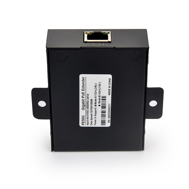
Choosing the right hardware dictates the stability of your entire network. Extenders fall into two distinct operational categories: active and passive. Active models are widely considered the gold standard for enterprise environments. They rely strictly on standard IEEE handshake protocols before ever transmitting voltage.
Active models offer profound benefits for long runs. They actively boost and regenerate the data signal at every hop. Furthermore, they verify that a valid Powered Device is connected at the other end. Power is only sent after this digital handshake completes. This intelligent verification prevents accidental surge damage to non-PoE devices plugged into the line.
Passive units operate entirely differently. They utilize simple capacitor storage to pass energy along. They offer a much lower entry cost, which makes them tempting for simple jobs. However, they carry significant inherent risks. Passive units force power blindly down the ethernet line. They do not check if the receiving device can handle the voltage. Using passive units for multi-node daisy chains is highly discouraged. They cause severe line instability and risk catastrophic equipment burnout.
You must also carefully assess environmental ratings. Standard indoor units will fail quickly if exposed to moisture or extreme heat. You should upgrade to IP67-rated hardened industrial models when deploying outdoors. These ruggedized units are mandatory for extreme temperature swings or direct-burial applications. They seal out dust, water, and debris to keep your line alive.
Long-distance networking does not have to remain strictly linear. Engineers use advanced deployment topologies to solve complex coverage gaps. One highly effective method is the drop-and-extend topology. This setup utilizes specialized 1-in-2-out hardware units. These branch the network into multiple physical directions.
A drop-and-extend setup provides massive installation flexibility. You can run a line 200 meters and power a security camera at that specific junction. The extender then continues pushing power and data down the line to another device at 400 meters. This prevents you from needing to run two separate 400-meter home runs from your main server room.
You might also consider using a PoE Switch featuring passthrough capabilities. A passthrough switch acts as an incredible mid-span solution. It operates entirely on upstream power from the main injector. The switch acts as both a Powered Device (PD) and Power Sourcing Equipment (PSE) simultaneously. You can place it in an attic or warehouse ceiling to split one long run into four smaller runs.
However, this approach carries a specific risk warning. You must watch out for the handshake protocol downgrade. A passthrough switch acts as a digital middleman. It may limit its downstream ports to a lower wattage standard, such as 802.3af (15W). It might do this regardless of how much power the main upstream injector provides. Always verify the passthrough capability limits before buying the hardware.
Your hardware is only as reliable as the cable connecting it. Skimping on physical infrastructure will guarantee network failure at long distances. You must follow strict physical cabling guidelines to maintain gigabit speeds and stable power over hundreds of meters.
Implement these core best practices for every installation:
Strictly Pure Copper: You must absolutely use Solid Bare Copper (UTP or STP) cables. Never use Copper Clad Aluminum (CCA) wiring. CCA cables feature an aluminum core coated in copper. They increase electrical resistance drastically. This heavily penalizes power delivery and will choke your extenders.
Deploy STP in High-EMI Zones: You must evaluate your environment for electromagnetic interference. Shielded Twisted Pair (STP) cables are mandatory when running lines through factories, near heavy machinery, or inside elevator shafts. The shielding preserves signal integrity over long distances by blocking external noise.
Avoid Spliced Connections: Every splice or punch-down keystone adds resistance. Run continuous, unbroken lengths of cable between each active node to minimize power loss.
Thermal Load Management: You should intentionally over-provision your upstream power source. Using a 90W injector for a 60W total load is a smart engineering practice. It keeps the main power supply running cool. Reducing thermal stress significantly extends the hardware lifespan.
Evaluating the difference between STP and UTP (Unshielded Twisted Pair) saves hours of troubleshooting. UTP works perfectly for quiet office environments. But industrial settings will destroy unshielded data packets. If your extended network drops offline every time an HVAC motor kicks on, inadequate shielding is your culprit.
Even the best copper setups eventually hit an absolute brick wall. You must recognize when stretching an ethernet line becomes bad engineering. When a physical run exceeds 1500 to 2000 feet, you have crossed the "too far" threshold. Pushing copper beyond this point guarantees dropped packets and insufficient voltage. You must abandon traditional extenders and embrace alternative technologies.
Fiber optic media converters offer the superior choice for these extreme distances. Fiber uses light instead of electricity, making it completely immune to EMI and voltage drop. You can run single-mode fiber for miles without losing a single megabit of speed. The main trade-off is power logistics. Fiber cannot carry electricity. You will absolutely require a local power source at the distant end to run the media converter and the edge device.
Point-to-Point (P2P) wireless bridges serve as another powerful alternative. They are the best choice for crossing parking lots, public roads, or physical obstacles. They completely eliminate the need for expensive trenching. However, you must carefully evaluate the site layout. P2P bridges require a perfectly clear line-of-sight between the two antennas. Just like fiber converters, they also require an independent power source at the remote location to function.
A network extender remains a highly effective, plug-and-play solution for stretching coverage limits. It effortlessly pushes your standard data runs up to 500 meters without requiring new electrical outlets. The technology works flawlessly provided the underlying math actually checks out. You must respect the strict physical limits of copper wiring.
Successful deployment heavily relies on mapping your total power budget beforehand. You must accurately account for the mandatory 5W parasitic tax exacted by every node in your chain. Investing in active hardware and pure solid copper infrastructure guarantees long-term stability. Passive devices and cheap aluminum cables will only lead to system failures.
Your next step is simple. Audit your edge device’s exact wattage requirements right now. Calculate your estimated distance, factor in the repeater losses, and size your initial injector accordingly. Careful upfront planning ensures your distant cameras and access points stay online securely.
A: No, true extenders do not require local AC outlets or external power bricks. They draw their operational power directly from the incoming ethernet line. They usually consume about 4 to 5 watts to run their internal components, passing the remaining energy forward.
A: Speeds can remain at full gigabit levels if you stay within the standard limits of up to four units. You must also use high-quality solid copper cables. Pushing beyond these limits will force the network to auto-negotiate, dropping speeds down to 100Mbps or 10Mbps.
A: Yes, provided it is a specific "PoE Passthrough" switch. Standard models require local AC power plugged into a wall. Passthrough switches operate entirely on line power drawn from the upstream network, acting as both a receiver and a power source.
A: This is usually caused by the voltage dropping below the critical 38V threshold. It can also stem from insufficient total wattage at the source injector. Using cheap, high-resistance Copper Clad Aluminum (CCA) cables is another major culprit for power failure.


