5F, W2, Chengxin Building , Tian An Shen Chuang Valley Industrial Center, Fenggang Town, Dongguan City, Guangdong Province,China 523681


DP9900LP
SDaPo
| Output Vdc: | |
|---|---|
| Availability: | |
| Quantity: | |
You are welcome to customize the POE modules of various size and connector and function.
The layout is after receive the research and development fee.
After ordering a certain number of modules (usually 5000 pieces no time limited), the R&D cost can be refund.
It takes 7-10 days to produce samples.After the sample is qualified, batch production.
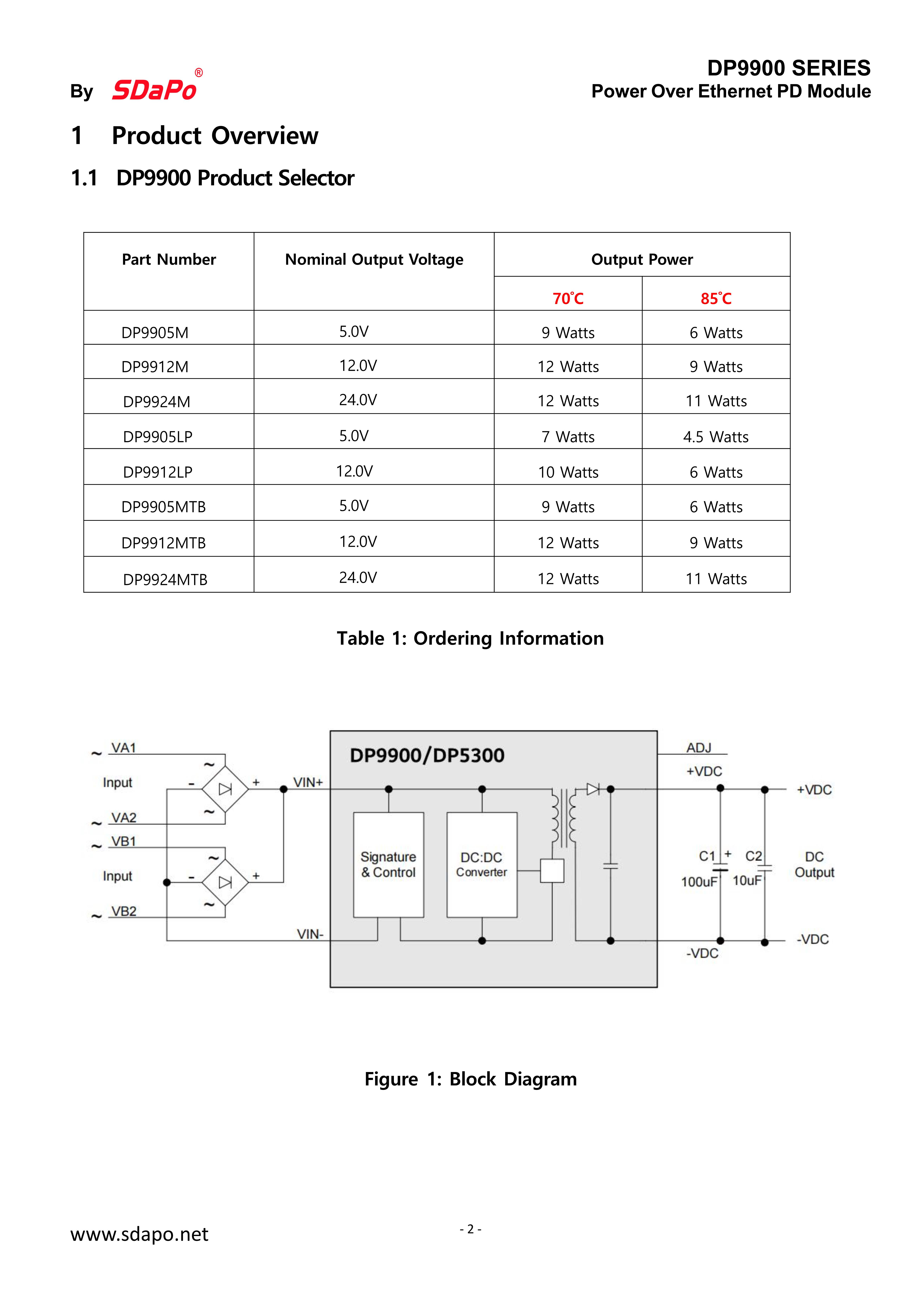
| No. | Part Number | Nominal Output Voltage | Output Power | PoE Standard | Temperature Range | PoE Modes | Isolation Voltage | Buy Sampls | |
| 70℃ | 85℃ | ||||||||
1 | DP9900M-5V | 5V | 9W | 6W | 802.3af | Industrial | Mode A / Mode B | 1.5kVrms | Inquiry us |
| 2 | DP9900M-12V | 12V | 12W | 9W | 802.3af | Industrial | Mode A / Mode B | 1.5kVrms | Inquiry us |
| 3 | DP9900M-24V | 24V | 12W | 11W | 802.3af | Industrial | Mode A / Mode B | 1.5kVrms | Inquiry us |
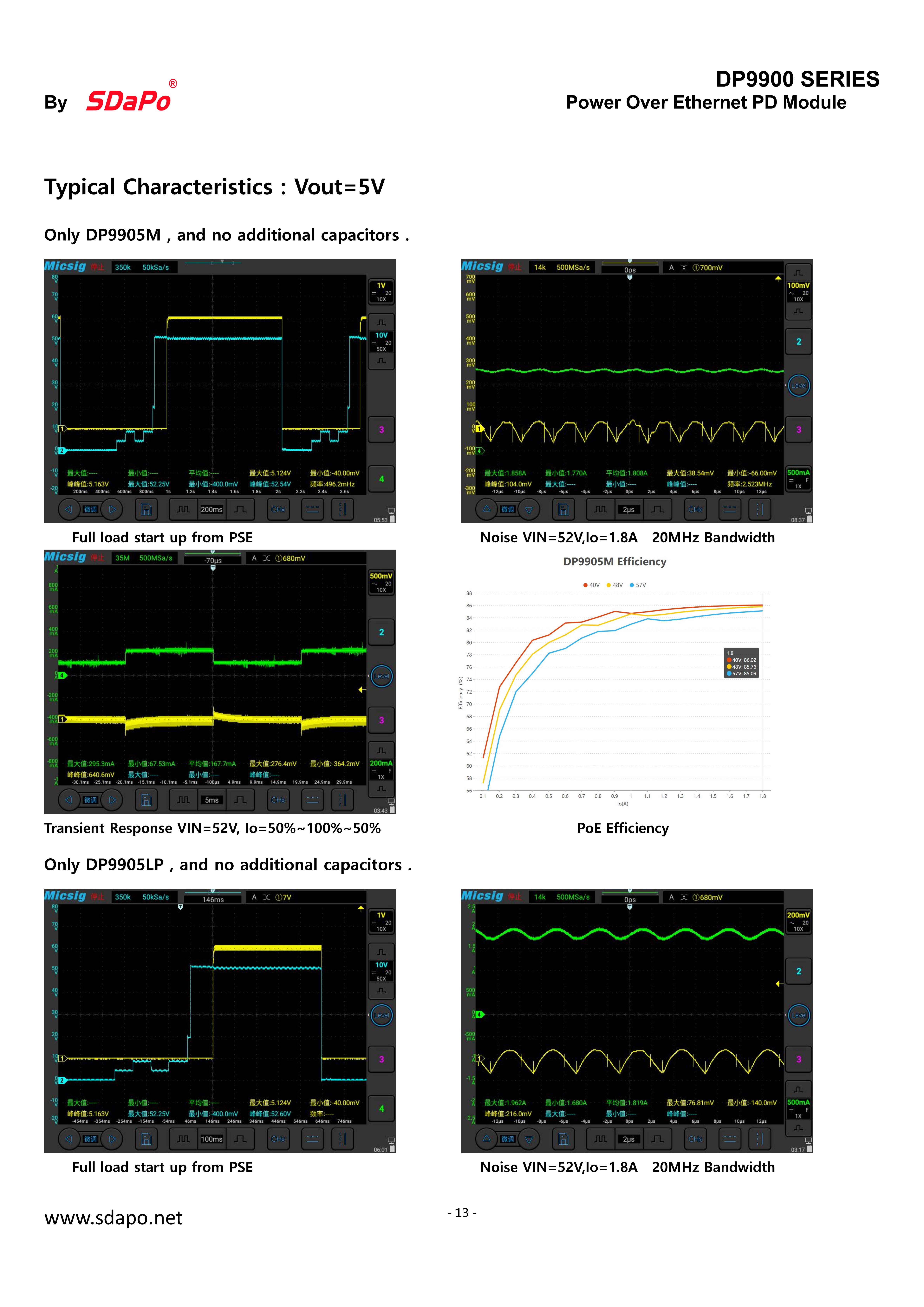
| 4 | DP9900LP-5V | 5V | 7W | 4.5W | 802.3af | Industrial | Mode A / Mode B | 1.5kVrms | Inquiry us |
| 5 | DP9900LP-12V | 12V | 10W | 6W | 802.3af | Industrial | Mode A / Mode B | 1.5kVrms | Inquiry us |
| 6 | DP9900MTB-5V | 5V | 9W | 6W | 802.3af | Industrial | Mode A / Mode B | 1.5kVrms | Inquiry us |
| 7 | DP9900MTB-12V | 12V | 12W | 9W | 802.3af | Industrial | Mode A / Mode B | 1.5kVrms | Inquiry us |
| 8 | DP9900MTB-24V | 24V | 12W | 11W | 802.3af | Industrial | Mode A / Mode B | 1.5kVrms | Inquiry us |
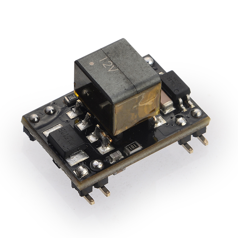
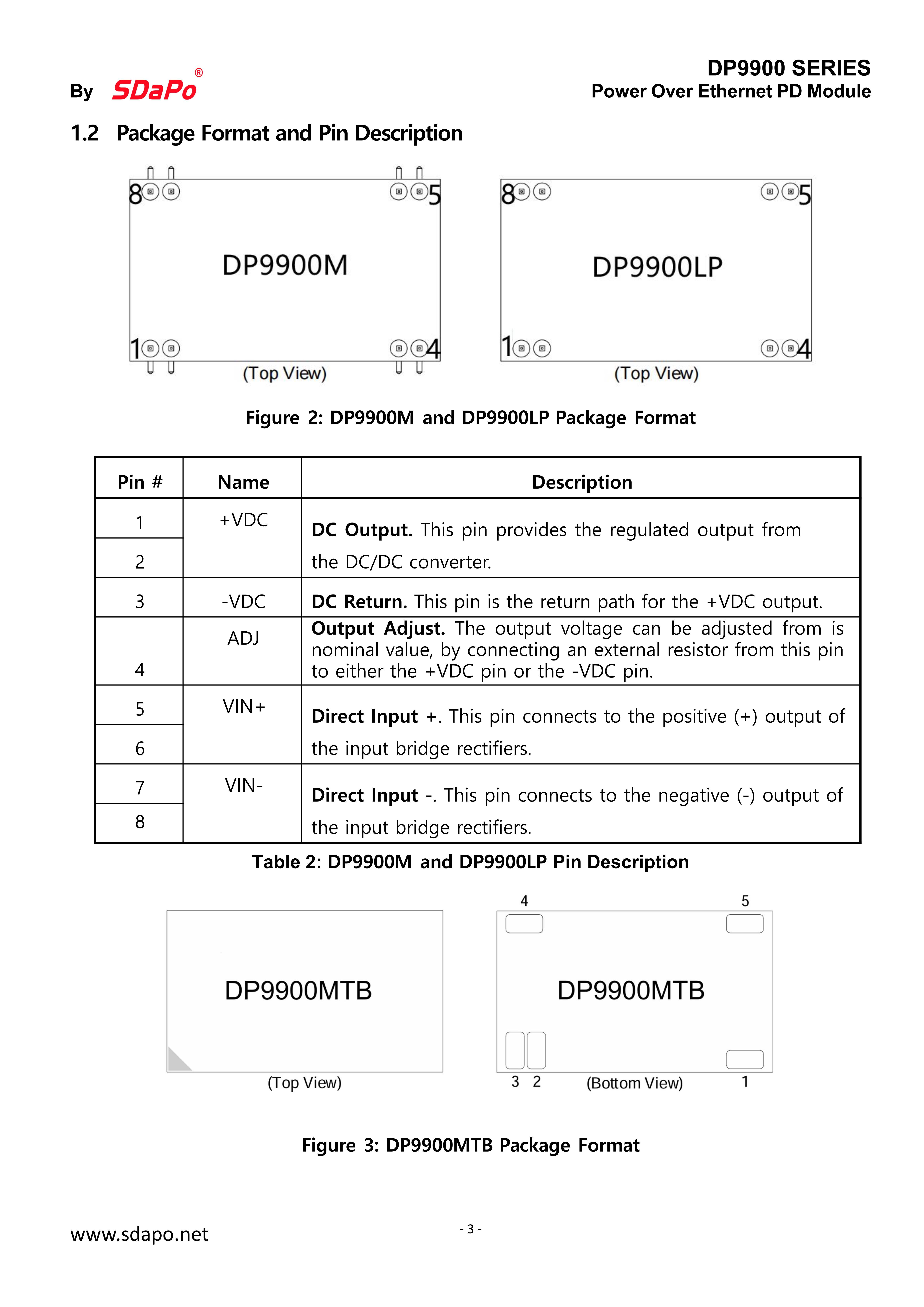
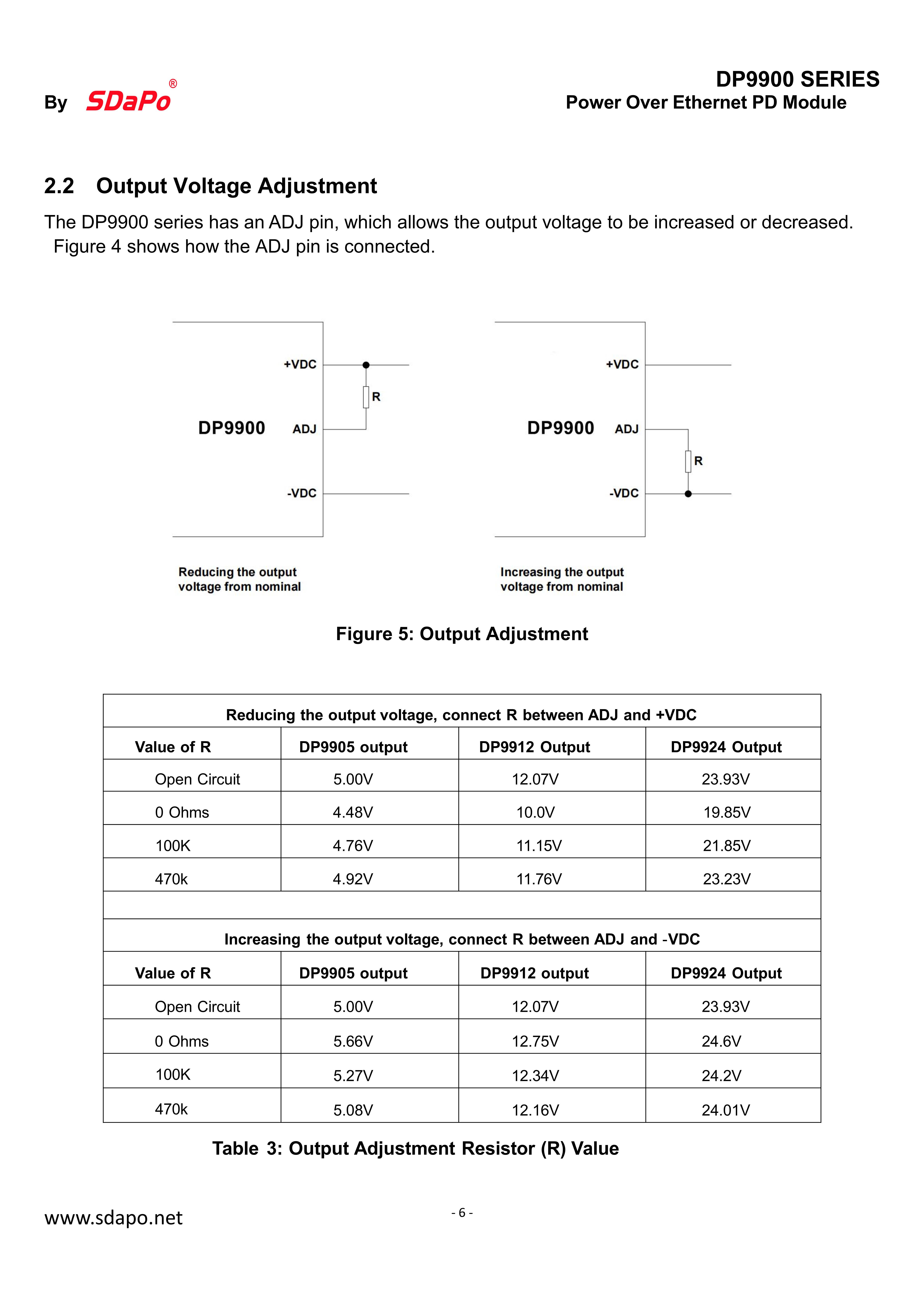
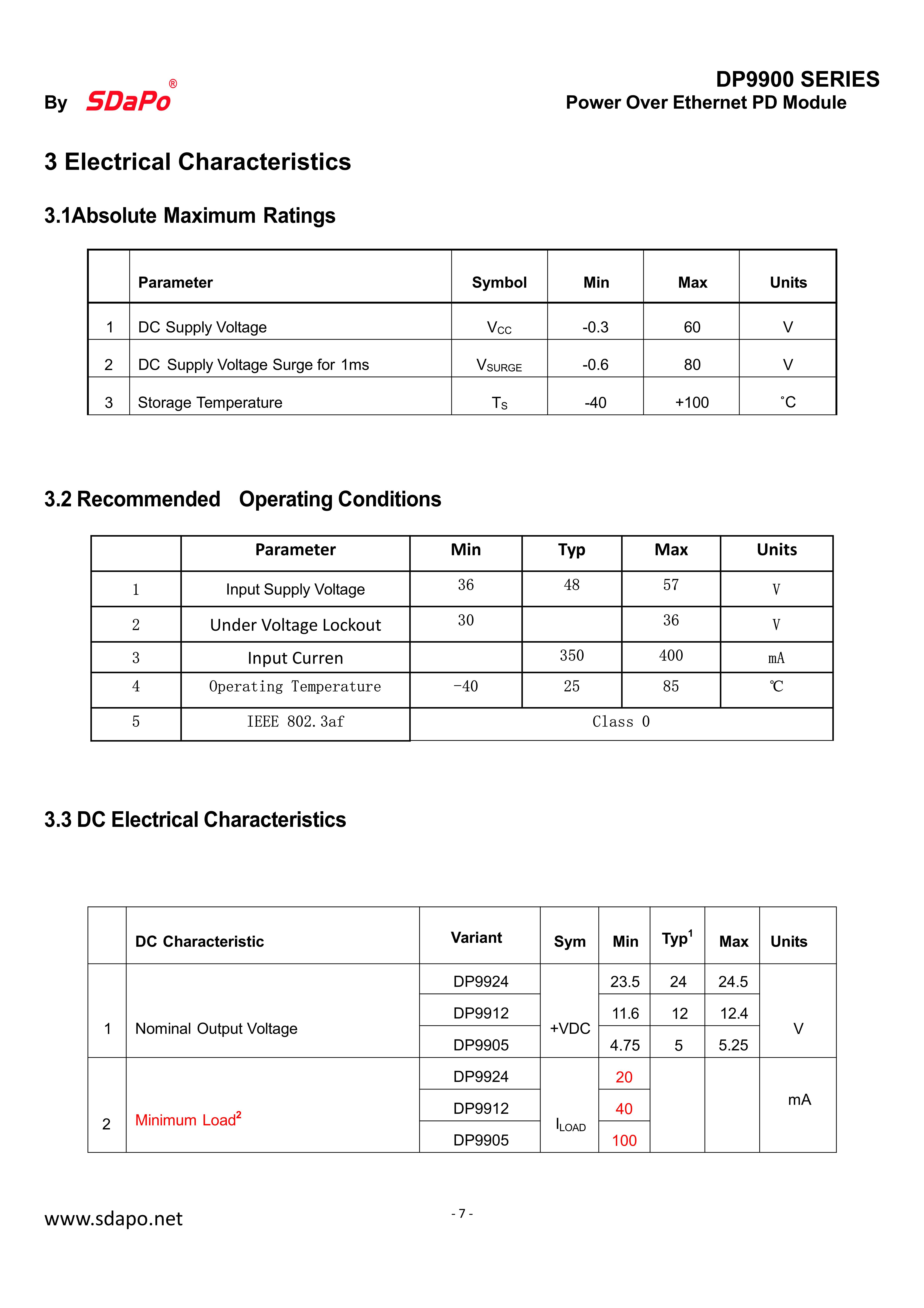
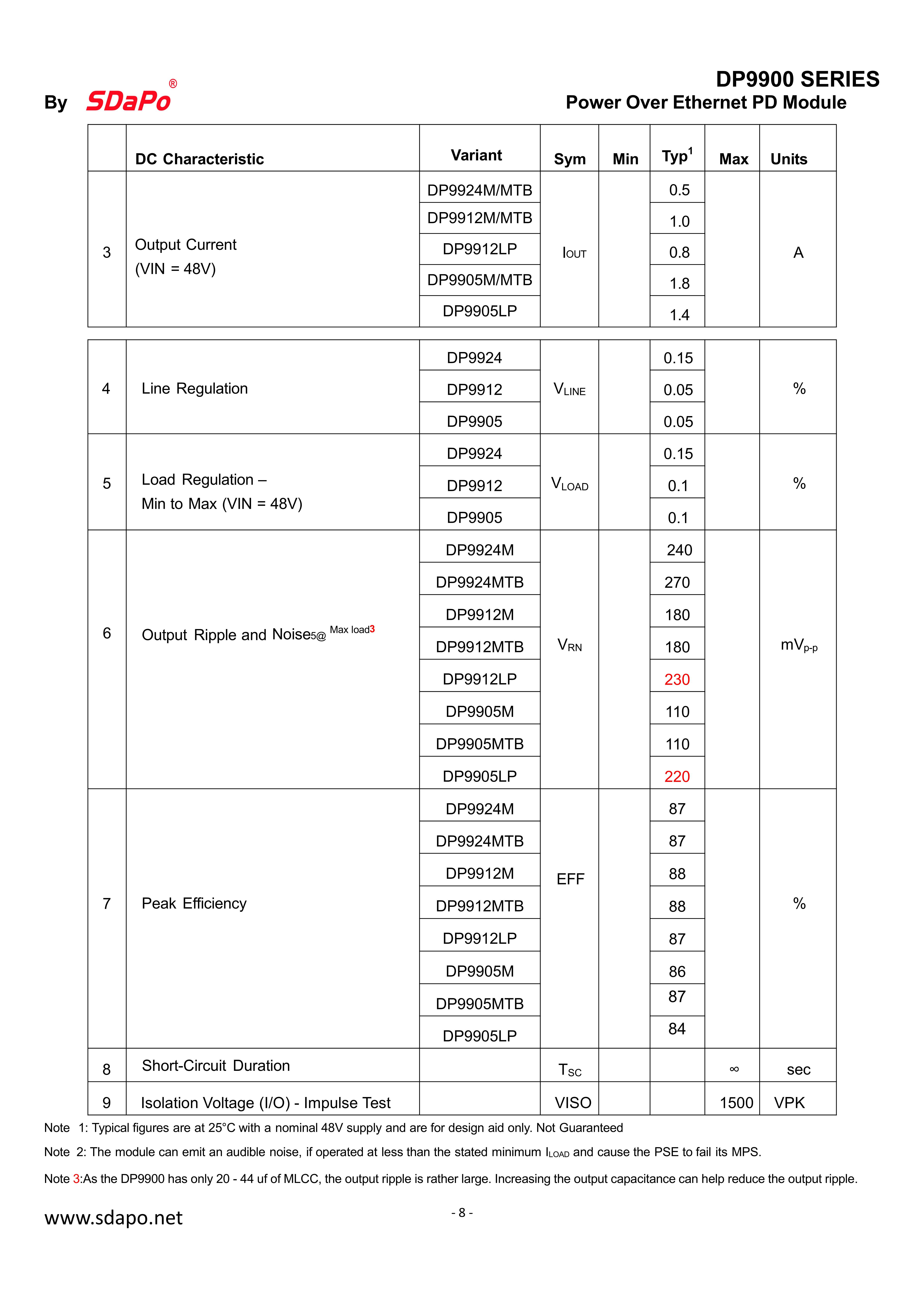
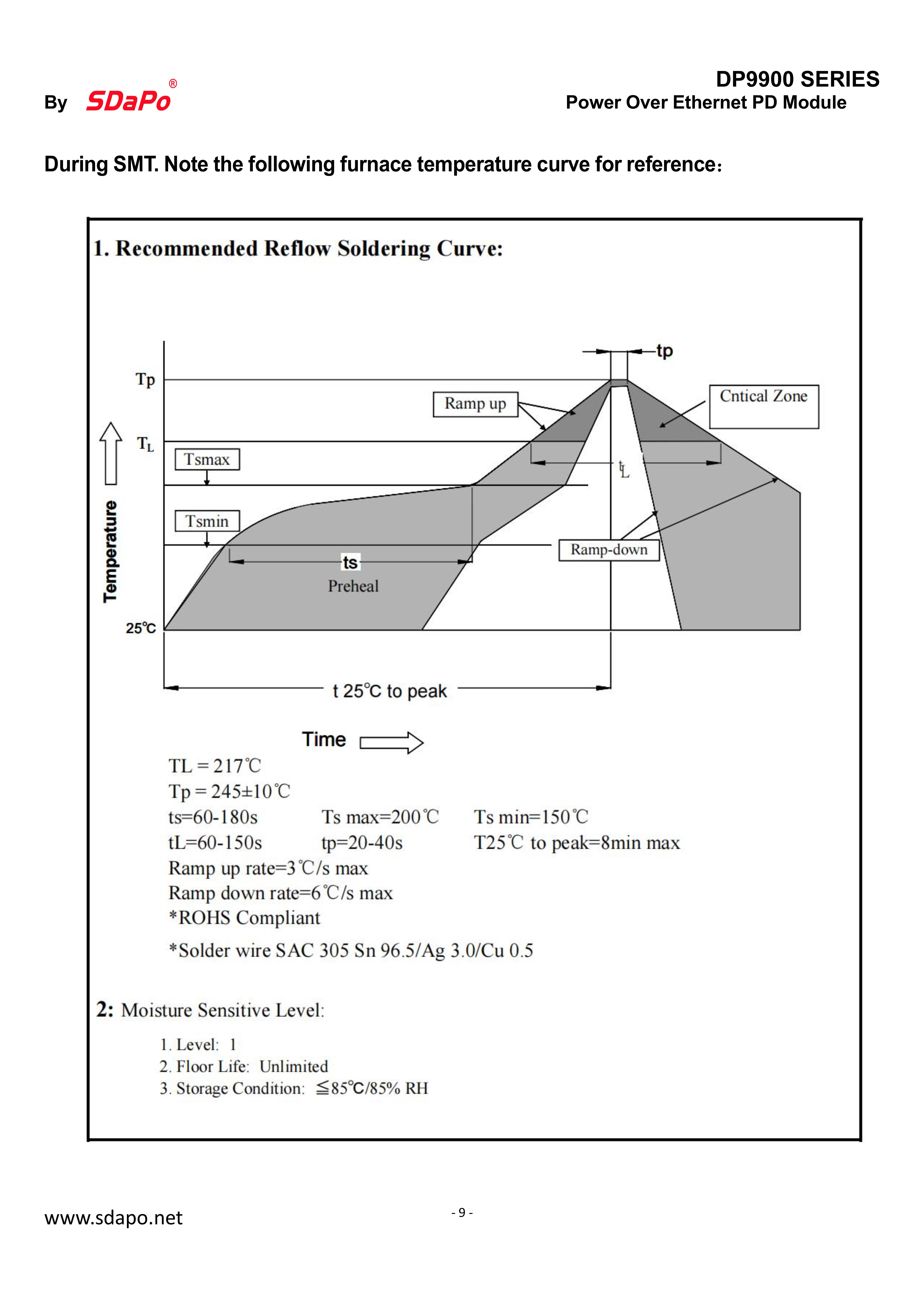
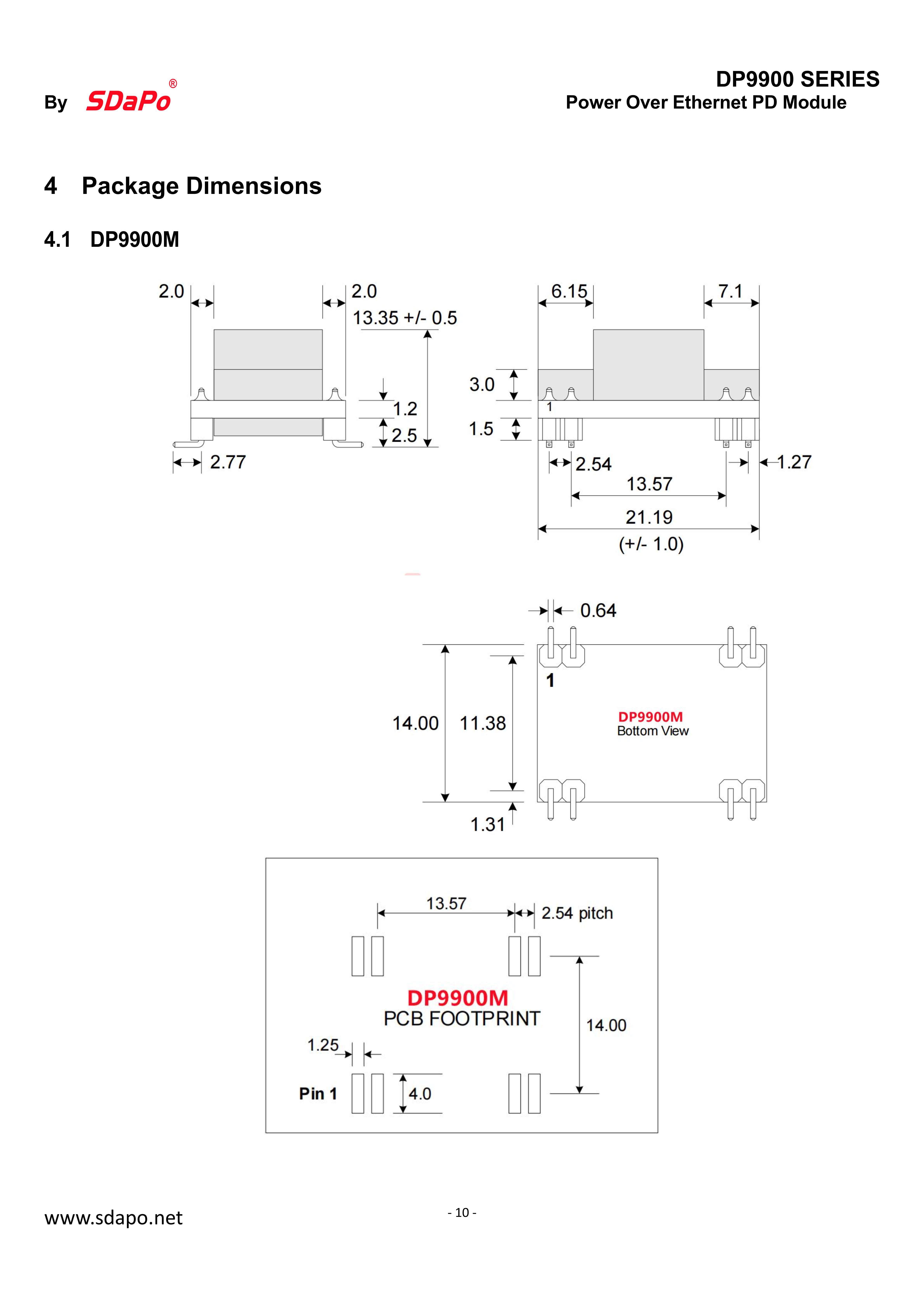
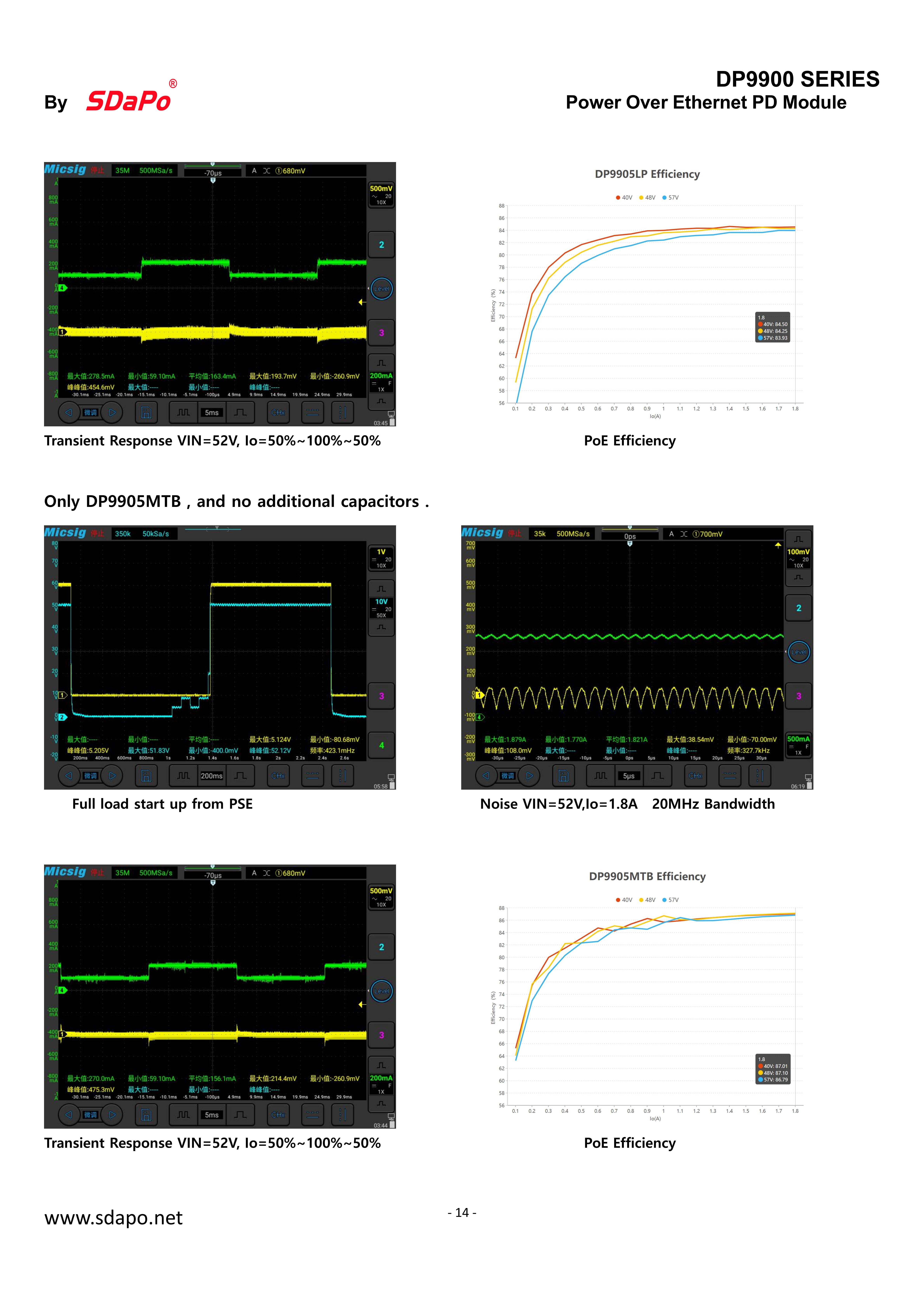
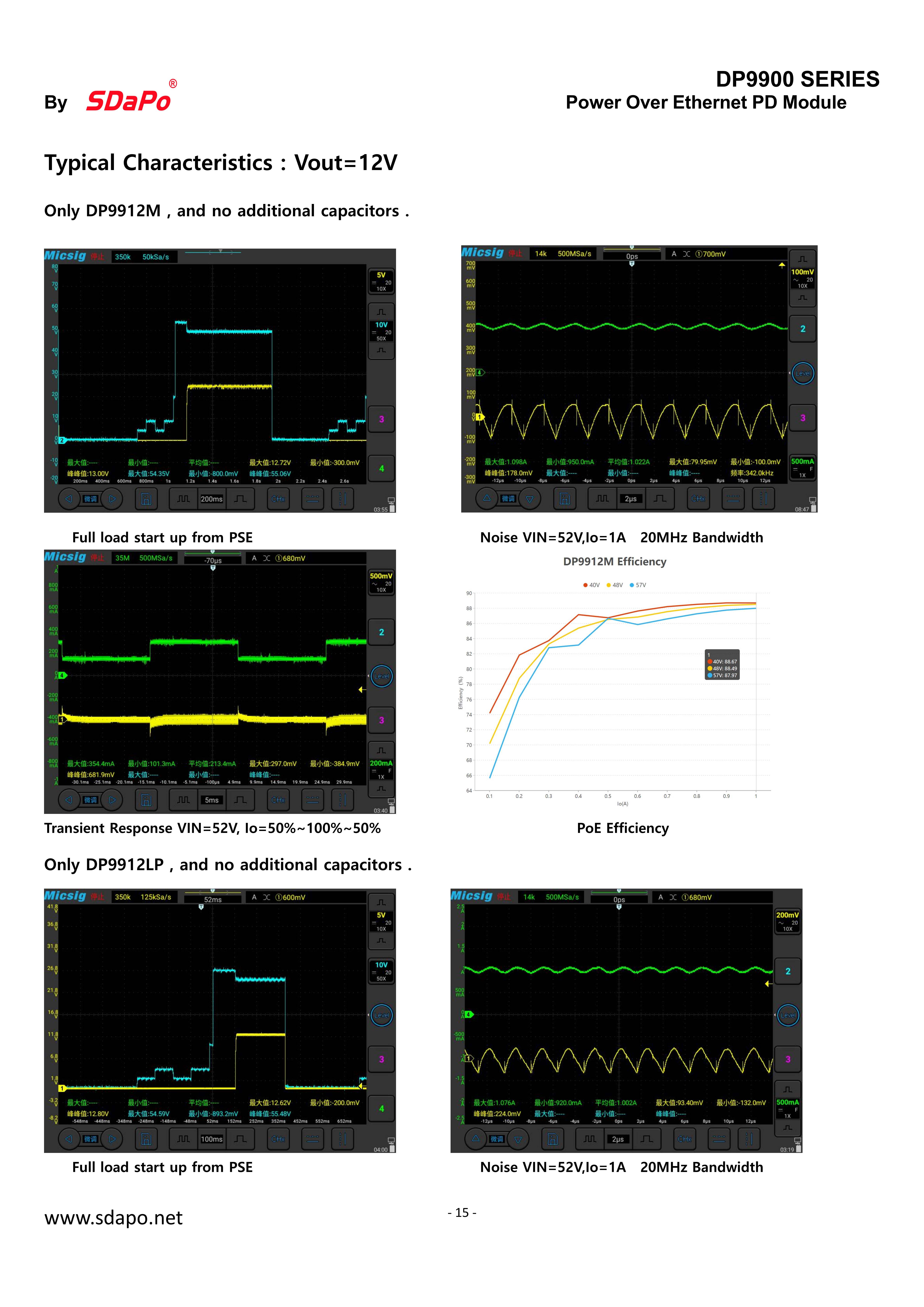
DP9900M-12V PoE Module
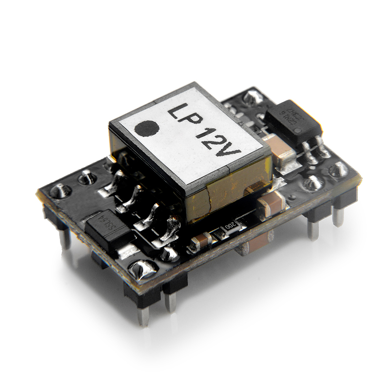
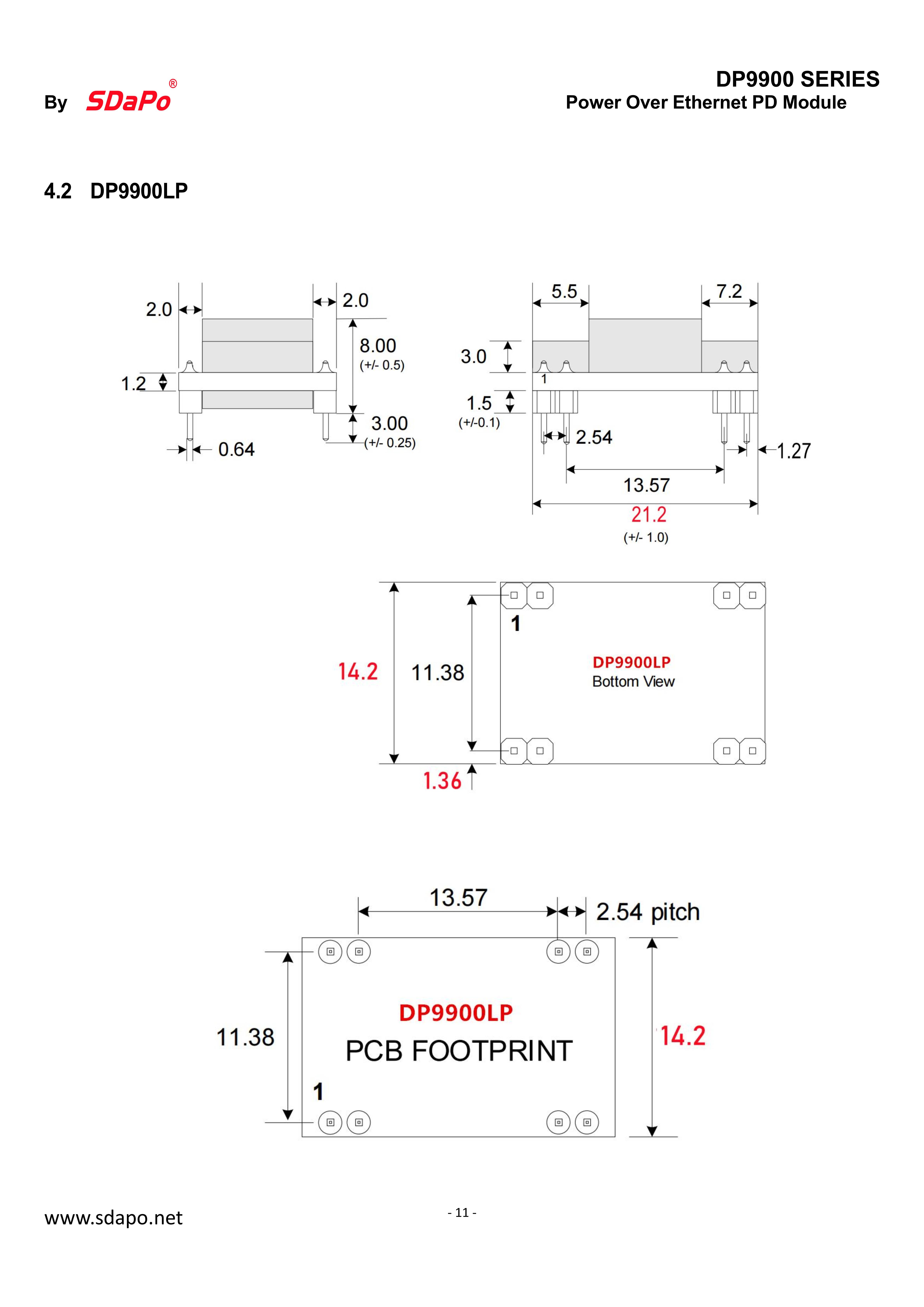
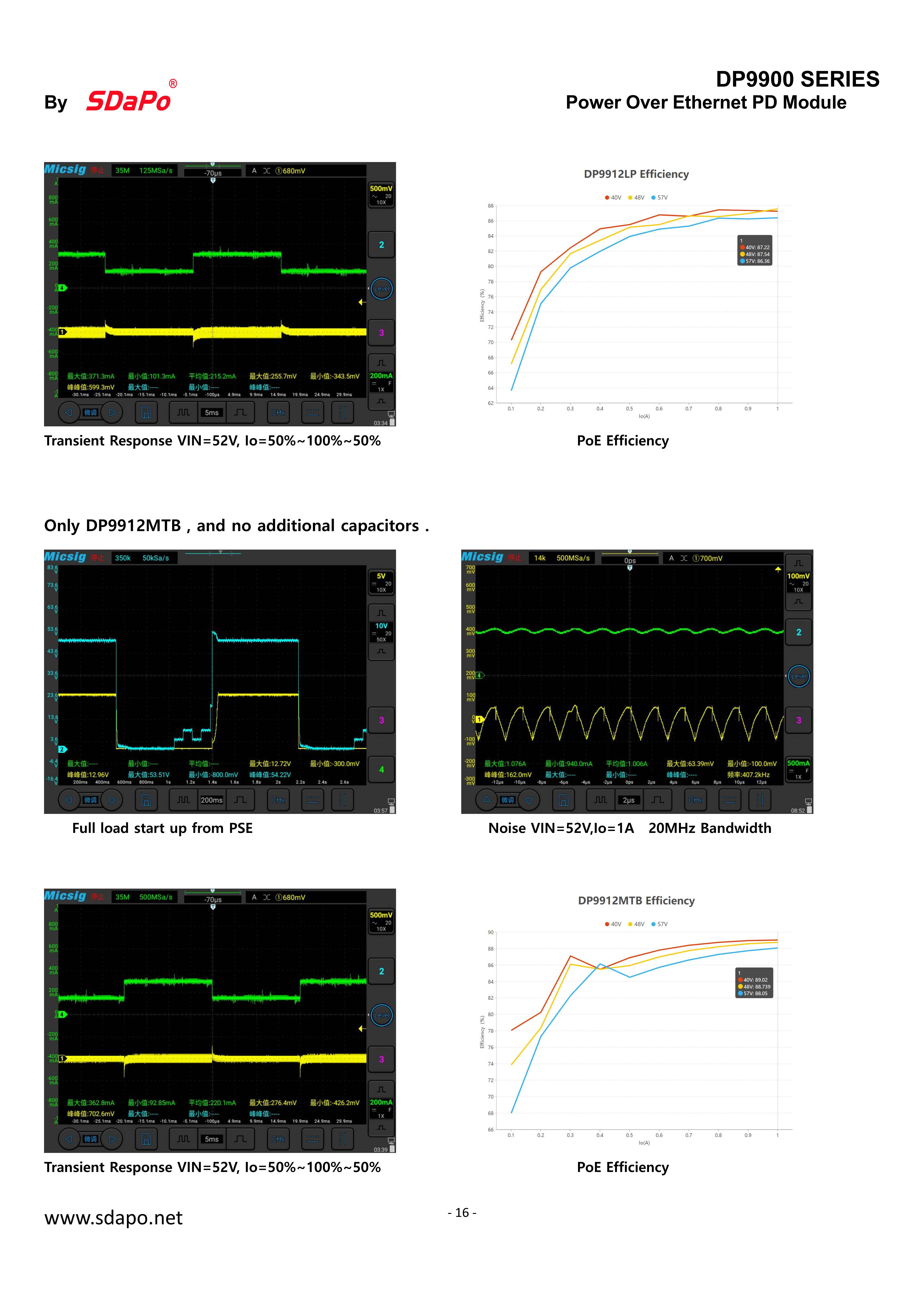
DP9900LP-12V PoE Module
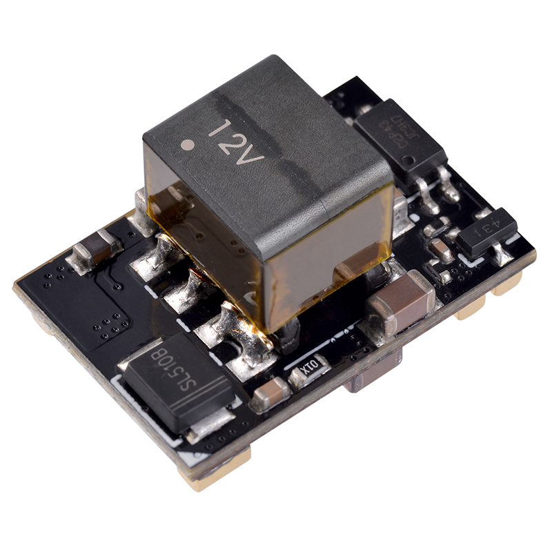
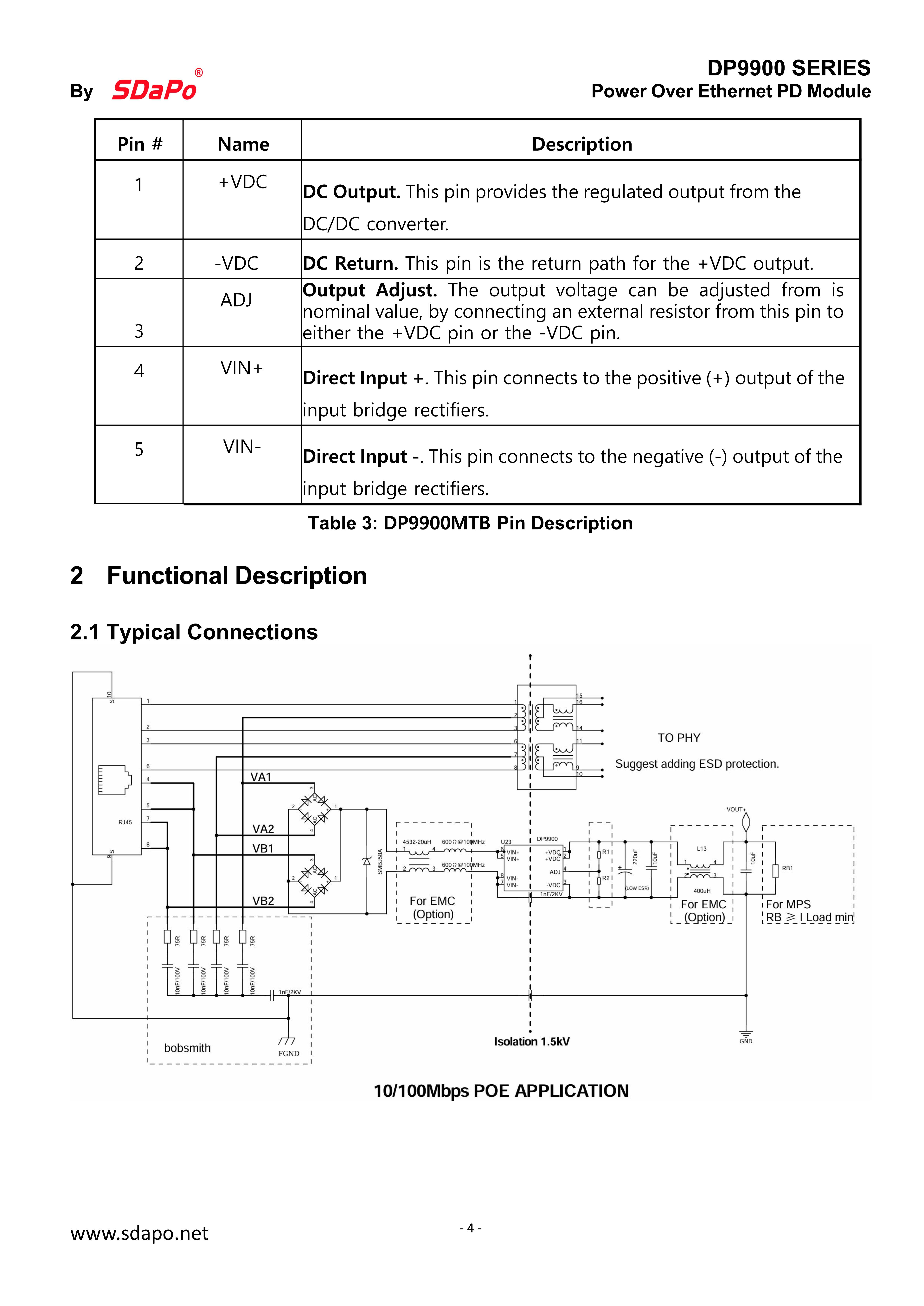
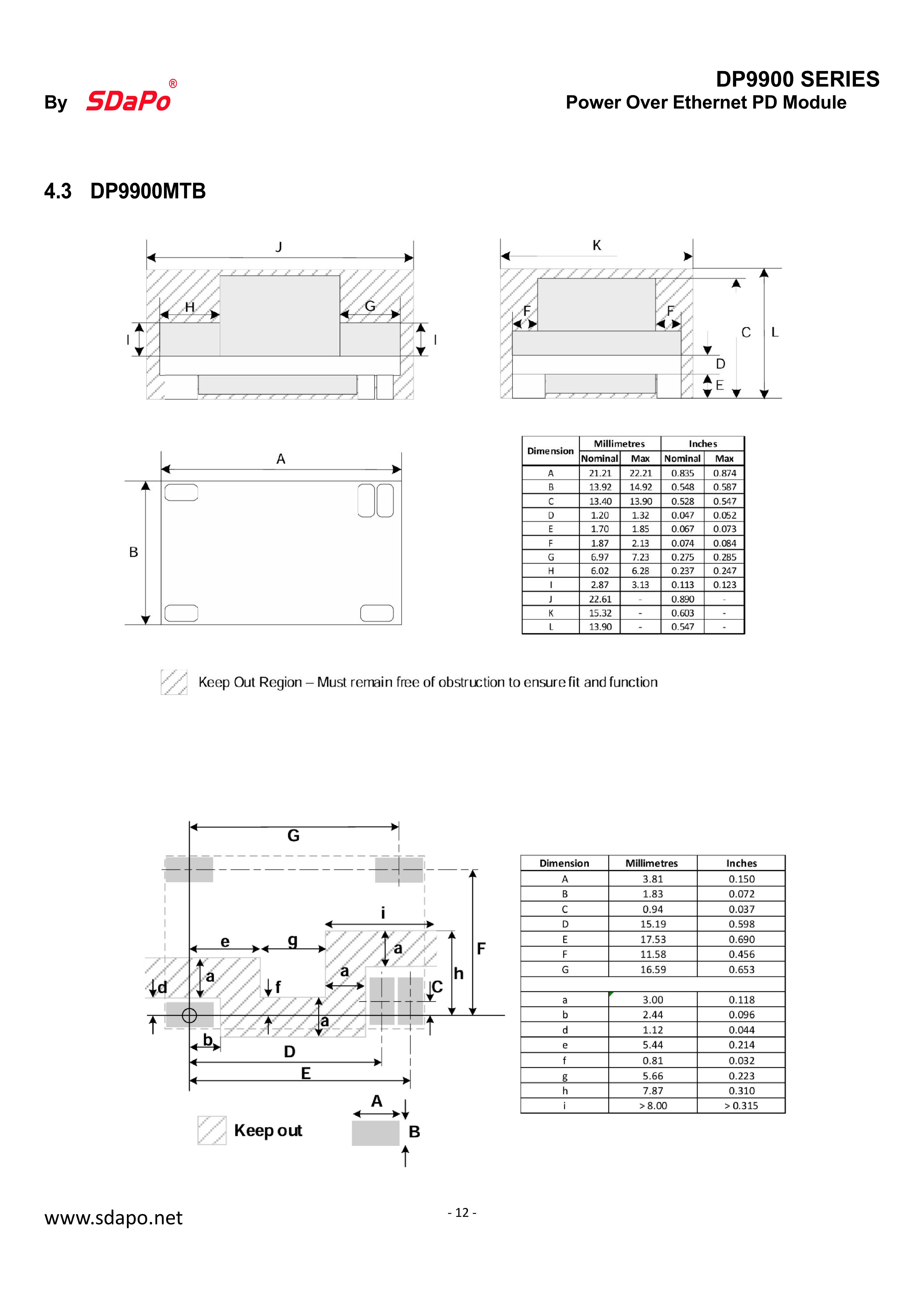
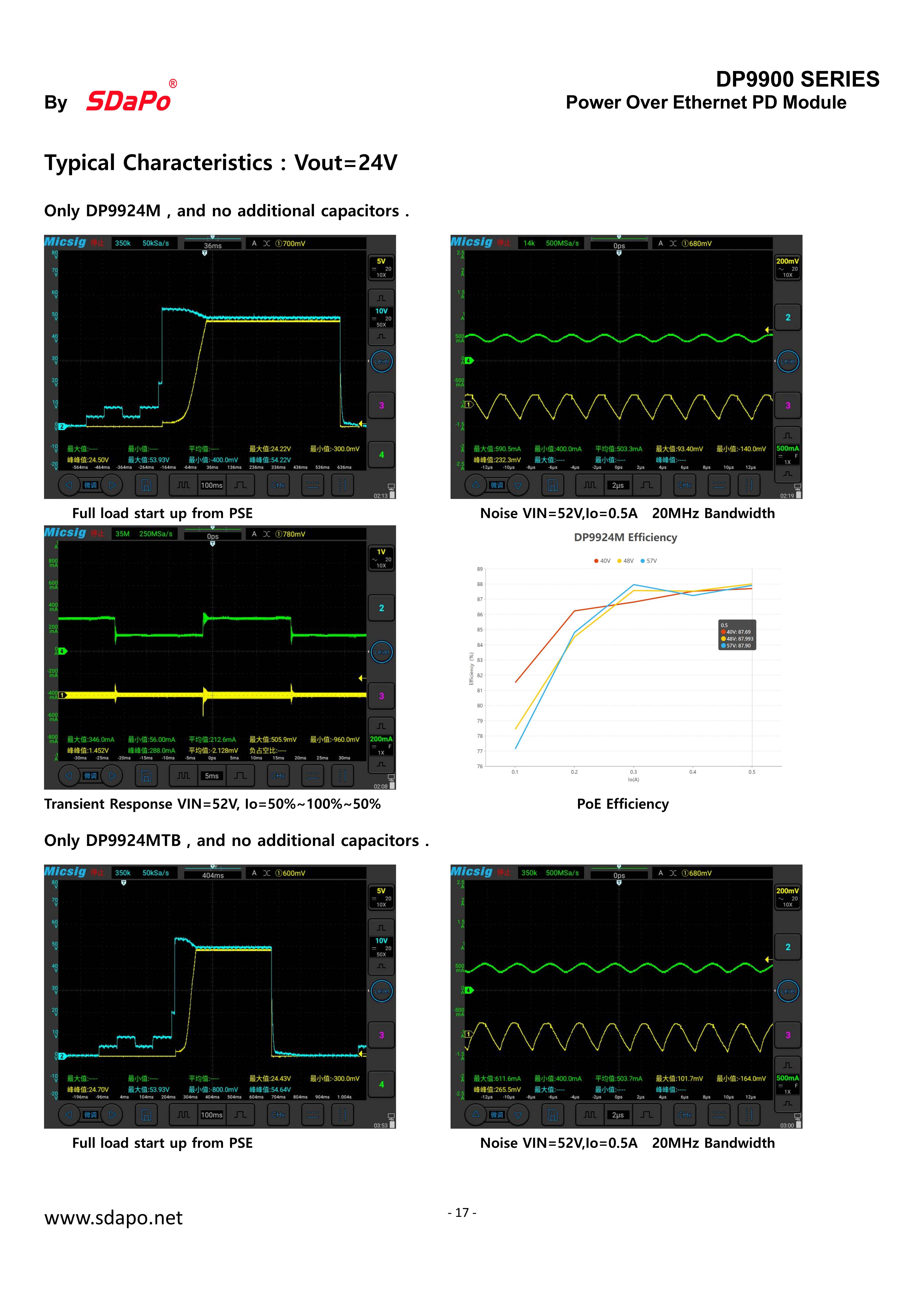
DP9900MTB-12V PoE Module
You are welcome to customize the POE modules of various size and connector and function.
The layout is after receive the research and development fee.
After ordering a certain number of modules (usually 5000 pieces no time limited), the R&D cost can be refund.
It takes 7-10 days to produce samples.After the sample is qualified, batch production.
| No. | Part Number | Nominal Output Voltage | Output Power | PoE Standard | Temperature Range | PoE Modes | Isolation Voltage | Buy Sampls | |
| 70℃ | 85℃ | ||||||||
1 | DP9900M-5V | 5V | 9W | 6W | 802.3af | Industrial | Mode A / Mode B | 1.5kVrms | Inquiry us |
| 2 | DP9900M-12V | 12V | 12W | 9W | 802.3af | Industrial | Mode A / Mode B | 1.5kVrms | Inquiry us |
| 3 | DP9900M-24V | 24V | 12W | 11W | 802.3af | Industrial | Mode A / Mode B | 1.5kVrms | Inquiry us |
| 4 | DP9900LP-5V | 5V | 7W | 4.5W | 802.3af | Industrial | Mode A / Mode B | 1.5kVrms | Inquiry us |
| 5 | DP9900LP-12V | 12V | 10W | 6W | 802.3af | Industrial | Mode A / Mode B | 1.5kVrms | Inquiry us |
| 6 | DP9900MTB-5V | 5V | 9W | 6W | 802.3af | Industrial | Mode A / Mode B | 1.5kVrms | Inquiry us |
| 7 | DP9900MTB-12V | 12V | 12W | 9W | 802.3af | Industrial | Mode A / Mode B | 1.5kVrms | Inquiry us |
| 8 | DP9900MTB-24V | 24V | 12W | 11W | 802.3af | Industrial | Mode A / Mode B | 1.5kVrms | Inquiry us |

DP9900M-12V PoE Module

DP9900LP-12V PoE Module

DP9900MTB-12V PoE Module


